Купуялык билдирүүсү: Сиздин купуялыгыңыз биз үчүн абдан маанилүү. Биздин компания сиздин жеке маалыматыңызды ачыкка чыгарууга уруксатыңыз менен ачыкка чыгарбоого убада берет.
Модели No.: NSO4GU3AB
ташуу: Ocean,Air,Express,Land
Төлөм түрү: L/C,T/T,D/A
Инкотерм: FOB,EXW,CIF
4GB 1600MHz 240-PIN DDR3 UDIMM
Тарыхы
|
Revision No. |
History |
Draft Date |
Remark |
|
1.0 |
Initial Release |
Apr. 2022 |
|
![]()
Маалымат таблицасына заказ кылуу
|
Model |
Density |
Speed |
Organization |
Component Composition |
|
NS04GU3AB |
4GB |
1600MHz |
512Mx64bit |
DDR3 256Mx8 *16 |
Сүрөттөө
Hengstar бузулбаган DDR3 SDRAM DIMMS (кош эмес кош маалыматтар ставкасы) DDR3 SDRAM түзмөктөрүн колдонгон DDR3 SDRAM түзмөктөрүн колдонгон төмөн кубаттуулук, жогорку ылдамдыктагы иштөө эс тутуму. Ns04gu3ab - бул 512м x 64 биттик эки наам 4GB DDR3-1600 CL11 1.5V SDR11 1.5V SDR11 1.5V 256 м х 8-бит фББА компоненттерине негизделген. SPD JEDEC стандартынын кечигүү DDR3-1600 11-11-11-жылдардагы 11-11-11 чейин программаланган. Ар бир 240-Пин Димм алтын менен байланыш манжаларын колдонот. SDRAM бузулбаган DIMM компьютерлер жана жумуш станциялары сыяктуу тутумдарга орнотулган негизги эс тутуму катары колдонууга арналган.
Өзгөчөлүктөрү
POWER жеткирүүсү: vdd = 1.5v (1.425V чейин 1.575V чейин)
vddq = 1.5V (1.425V чейин 1.575V чейин)
800MHZ FK 1600MB / SEC / PIN үчүн
8 Көзкарандысыз Ички Банкы
Кол өнөрчүлүк CAS ЛЕНТИНИ: 11, 10, 9, 8, 7, 6
Колгосуз калган кечигүү: 0, CL - 2 же CL - 1 саат
8 биттик алдын ала алып келүү
Бурст Length: 8
bi-багытындагы дифференциалдык маалыматтар стробе
индин (өз алдынча) калибрлөө; ZQ PIN (RZQ: 240 OH 1% oh 1%)
Odt PIN менен токтотуу DEM токтотуу
7,8 ° C, 3,9ус 85 ° C, 85 ° C (95 ° C)
Asynchronous Resus
Data-Output Drive
Топология менен
pcb: Бийиктиги 1.18 "(30мм)
rohs ылайыктуу жана галоген
Негизги убакыт параметрлери
|
MT/s |
tRCD(ns) |
tRP(ns) |
tRC(ns) |
CL-tRCD-tRP |
|
DDR3-1600 |
13.125 |
13.125 |
48.125 |
2011/11/11 |
Дарек үстөлү
|
Configuration |
Refresh count |
Row address |
Device bank address |
Device configuration |
Column Address |
Module rank address |
|
4GB |
8K |
32K A[14:0] |
8 BA[2:0] |
2Gb (256 Meg x 8) |
1K A[9:0] |
2 S#[1:0] |
PIN сүрөттөөлөр
|
Symbol |
Type |
Description |
|
Ax |
Input |
Address inputs: Provide the row address for ACTIVE commands, and the column |
|
BAx |
Input |
Bank address inputs: Define the device bank to which an ACTIVE, READ, WRITE, or |
|
CKx, |
Input |
Clock: Differential clock inputs. All control, command, and address input signals are |
|
CKEx |
Input |
Clock enable: Enables (registered HIGH) and disables (registered LOW) internal circuitry |
|
DMx |
Input |
Data mask (x8 devices only): DM is an input mask signal for write data. Input data is |
|
ODTx |
Input |
On-die termination: Enables (registered HIGH) and disables (registered LOW) |
|
Par_In |
Input |
Parity input: Parity bit for Ax, RAS#, CAS#, and WE#. |
|
RAS#, |
Input |
Command inputs: RAS#, CAS#, and WE# (along with S#) define the command being |
|
RESET# |
Input |
Reset: RESET# is an active LOW asychronous input that is connected to each DRAM and |
|
Sx# |
Input |
Chip select: Enables (registered LOW) and disables (registered HIGH) the command |
|
SAx |
Input |
Serial address inputs: Used to configure the temperature sensor/SPD EEPROM address |
|
SCL |
Input |
Serial |
|
CBx |
I/O |
Check bits: Used for system error detection and correction. |
|
DQx |
I/O |
Data input/output: Bidirectional data bus. |
|
DQSx, |
I/O |
Data strobe: Differential data strobes. Output with read data; edge-aligned with read data; |
|
SDA |
I/O |
Serial |
|
TDQSx, |
Output |
Redundant data strobe (x8 devices only): TDQS is enabled/disabled via the LOAD |
|
Err_Out# |
Output (open |
Parity error output: Parity error found on the command and address bus. |
|
EVENT# |
Output (open |
Temperature event: The EVENT# pin is asserted by the temperature sensor when critical |
|
VDD |
Supply |
Power supply: 1.35V (1.283–1.45V) backward-compatible to 1.5V (1.425–1.575V). The |
|
VDDSPD |
Supply |
Temperature sensor/SPD EEPROM power supply: 3.0–3.6V. |
|
VREFCA |
Supply |
Reference voltage: Control, command, and address VDD/2. |
|
VREFDQ |
Supply |
Reference voltage: DQ, DM VDD/2. |
|
VSS |
Supply |
Ground. |
|
VTT |
Supply |
Termination voltage: Used for control, command, and address VDD/2. |
|
NC |
– |
No connect: These pins are not connected on the module. |
|
NF |
– |
No function: These pins are connected within the module, but provide no functionality. |
Кошумча маалыматтар : Төмөндө PIN-мүнөздөмөлөрдүн таблицасы бардык DDR3 модулдары үчүн бардык мүмкүн болгон казыктардын тизмеси келтирилген. Бардык казыктардын болушу мүмкүн бул модулда колдоого алынбайт. Бул модулга мүнөздүү маалымат алуу үчүн PIN тапшырмаларды караңыз.
Функционалдык блок диаграммасы
4GB, 512MX64 Модул (X8 2)


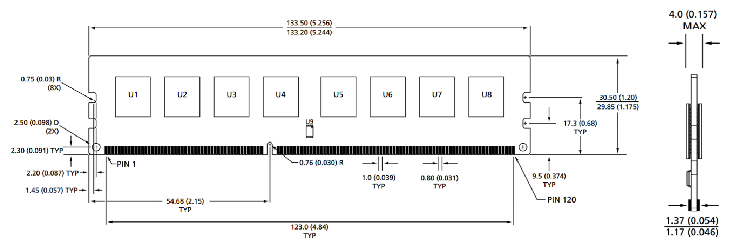
Модулдун өлчөмдөрү
Алдыңкы көрүнүш

Алдыңкы көрүнүш

Кошумча маалыматтар:
1.All Өлчөмдөрү миллиметр (дюйм); Макс / мин же мүнөздүү (TOP) белгилеген жерде.
2. Бардык өлчөмдөр боюнча ± 0.15mm башкача көрсөтүлбөсө.
3. Өлчөмдүү диаграмма маалымдама гана.
Продукт Categories : Industrial Smart Module Аксессуары


Купуялык билдирүүсү: Сиздин купуялыгыңыз биз үчүн абдан маанилүү. Биздин компания сиздин жеке маалыматыңызды ачыкка чыгарууга уруксатыңыз менен ачыкка чыгарбоого убада берет.

Сиз менен тезирээк байланышып турсаңыз болот
Купуялык билдирүүсү: Сиздин купуялыгыңыз биз үчүн абдан маанилүү. Биздин компания сиздин жеке маалыматыңызды ачыкка чыгарууга уруксатыңыз менен ачыкка чыгарбоого убада берет.